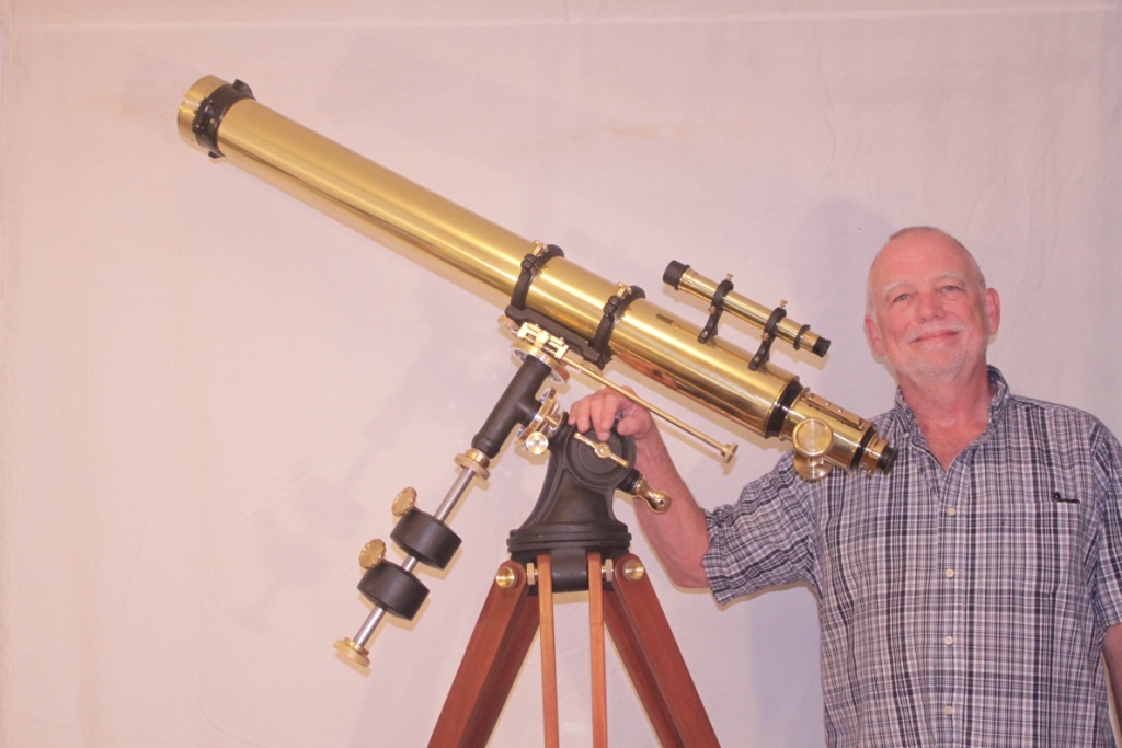
Dave and Replica Alvan Clark
This page details the construction of the mount and accessories of my Alvan Clark Replica Telescope. If you are interested in how I made the lens please see Making My First Lens.
My replica mount is probably most similar in size to the Clark #4 mount but has features usually found only on the larger Clark mounts such as setting circles and slow motions. The head weighs about 22 lbs., the scope is 20 lbs., weights are 11 lbs. each and the tripod is 18 lbs. The Clark #4 mount was actually designed by Carl Lundin for the Alvan Clark Corporation. To duplicate it I worked strictly from photographs I found online and a couple of diagrams in the superb book, Alvan Clark and Sons Artists in Optics by Warner and Ariail.
To understand these images, you may want to watch the Youtube videos before reading further. They are at: Alvan Clark Replica Tour and Alvan Clark Replica Teardown
During design and construction I made my best guesses as to the functional details of the mount. My first version did not have slow motions but I found that the mount was a pleasure to use in that configuration. I discovered that I could adjust the friction to be “just right” to smoothly move the scope around while holding position nicely when released. Tracking the motion of the stars was easy with a little nudge. When I added the slow motions I found that balancing the friction made things a bit more complicated.
I could not find any evidence of a “locking mechanism” on the Lundin mount to make the slow motion gear lock to the axis. As a result, my mount relies on differential friction. I am not sure if this the way a genuine Lundin mount works but on mine the friction between the gear and the shaft is higher than between the axis and the mount. This system works pretty well, as long as the telescope is well balanced. In fact, the function of this mount is very similar to a Losmandy G11 mount. Of course a Losmandy uses twentieth century engineering with modern needle bearings, ball bearings, spring washers, etc. Losmandy mounts are renowned for their quality engineering and are a genuine pleasure to use. This replica is much more primitive but the basic idea is similar. Though my imitation Lundin mount is nowhere near as sophisticated as a Losmandy, it still functions well.
Here are several sets of images that show you how the construction went. They should be self-explanatory to anyone with a bit of machining experience.
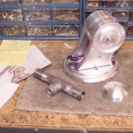
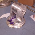
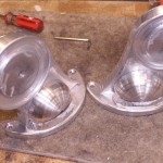
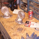
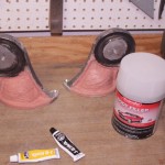
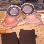
Making the Trunnions
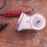
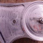
I don’t have a small home foundry so I had to imitate the Lundin castings as best I could without sacrificing any strength. I am pretty sure the Clark Mounts are made of cast iron. My replica is made of a series of aluminum pieces, bolted together. I used some JB Weld Steel Stick to augment the sculpting of the more difficult shapes. I applied some JB Weld Epoxy for a filler and smoother. A bit of grinding and shaping got me close to the desired form. A bit of Bondo allowed me to smooth the shapes more evenly and filled some left-over gaps, holes and small imperfections. A lot of sanding got the part to the final form. The entire process was half machining and half sculpting. Don’t get the wrong impression. These parts are not “made of Bondo”. If you hit one of these pieces hard with a hammer, you will break off a little paint and some flecks of Bondo but you will not break the part. If you whack it enthusiastically with a sledge hammer you may chip off some of the steel stick and you will severely dent or bend the aluminum. But, you will not break it apart. The same punishment might actually crack a real Alvan Clark casting, or even break it.

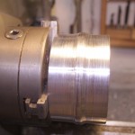
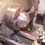

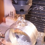
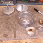
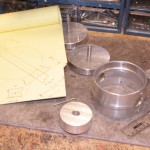

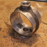
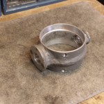


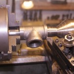
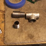
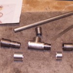
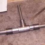
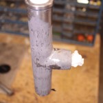
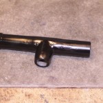
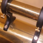
Making the Tee
I used steel pipe with a tee union and several sections of pipe. First I machined the end pieces ( also pipe unions) and the tee to accept the brass bearings. A little turning in the lathe took off some rough external ridges as well. Then I turned a couple of aluminum sleeves to give the assembly a uniform thickness and joined the pieces by their own screw threads solidly locked in place with JB Weld. Then I used some more JB Weld to smooth it further. Some sanding finished it up ready for paint.
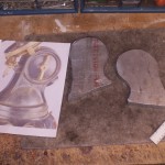
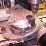
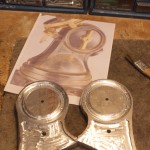
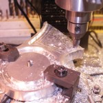
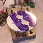
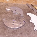
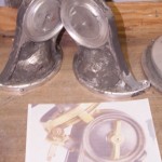
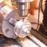
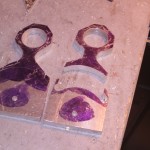
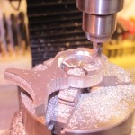
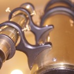
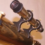
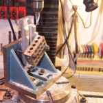
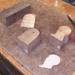
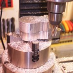
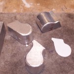
Making the Finder mounts
I wanted the curve at the base to be a perfect match to the tube so I cut it using my rotating table on the mill. The rest was rough cutting with a band saw and lot and lots of filing and sanding.
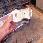
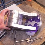
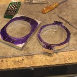
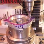
Making the Saddle and Tube Mounting Rings
I wanted something that was at least vaguely like some Alvan Clark rings I have seen in pictures, probably on a larger scope. These are straightforward compression rings that stay permanently on the tube, though they can be loosened to slide the tube for ballance when the scope is on the mount or even removed if necessary. This design makes it very easy to mount the tube (with rings) with just a couple of thumb nuts. While making the saddle, I wanted a nice fit to the rings so I made a rather elaborate set-up on my rotating table. This may have been an unnecessary effort, but at least this way the fit is guaranteed.
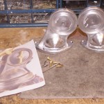
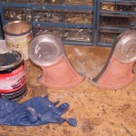
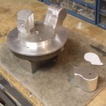
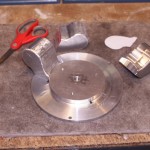
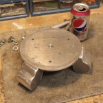
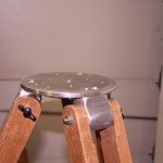
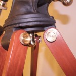
Making the Tripod Head
This was easy and fun. This is just a few lumps of aluminum, shaped to a graceful curve and bolted to a nice beefy aluminum plate. A little JB Weld at the seams to smooth things out and it looks a lot like a casting. It’s really no coincidence that these things look so much like castings. The original Clark workers certainly made the molds using wooden parts shaped and formed in nearly the same way that I shape my aluminum pieces.
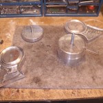
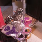
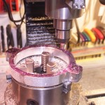
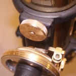
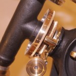
Making the setting circles and Slow Motion
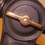
These are slices of nice brass tube press fit onto aluminum disks. The engraving was done using a very sharp engraving bit in my mill and controlling the position of the circle with a dividing head. I made a guide for the number stamps. You could actually use these if necessary.
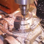
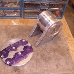
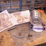
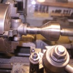
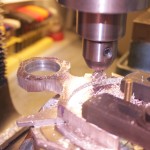
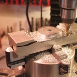
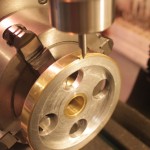
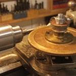
Making a Worm Gear I made the slow motion gears using the “free hobbing” technique. I used a dividing head on my mill to make slight little cuts in the gear blank at the appropriate locations. This goring operation then allowed the tap to engage the blank and get started with the actual cutting operation. A standard ½’ – 13 tap was set up to turn and the brass gear blank was “run into” the spinning tap (acting as a hob). The second picture is a free cutting operation on a different gear but is based on the same principles. There are videos on Youtube that show this nicely. This technique is pretty easy and fun for an amateur machinist and saves a lot of money and time over alternative techniques.

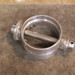
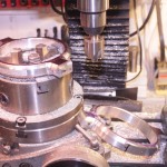
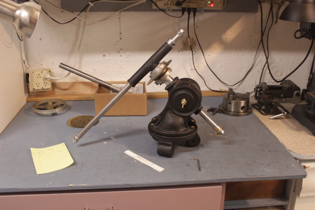
Completed Mount Head Assembly
This picture shows the completed assembly at an early stage. At this point it was working pretty well and I tried it out with the telescope. I was shocked to see how well these inexpensive bronze bearings worked and the friction system as a whole is buttery smooth.
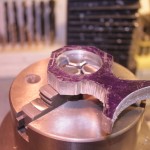
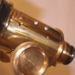
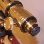
Making the Crayford Focusser.
This was easy and fun to machine. You can see the slots in the outer tube. I don’t know where I got those ball bearings but it just proves that it’s wise to keep everything. I am still amazed at how smooth this is.
Acknowlegements: This project was inspired by Al Hall and Dick Parker and their wonderful work at Seagrave Observatory in rebuilding the Alvan Clark Clock Drive http://www.theskyscrapers.org/8-inch-alvan-clark-telescope