Here’s an update on my Unitron Weight Drive restoration.
My goal was to complete the replication of the components shown in these pictures:

I have a complete weight drive system with nearly all original components, on the left in this picture.
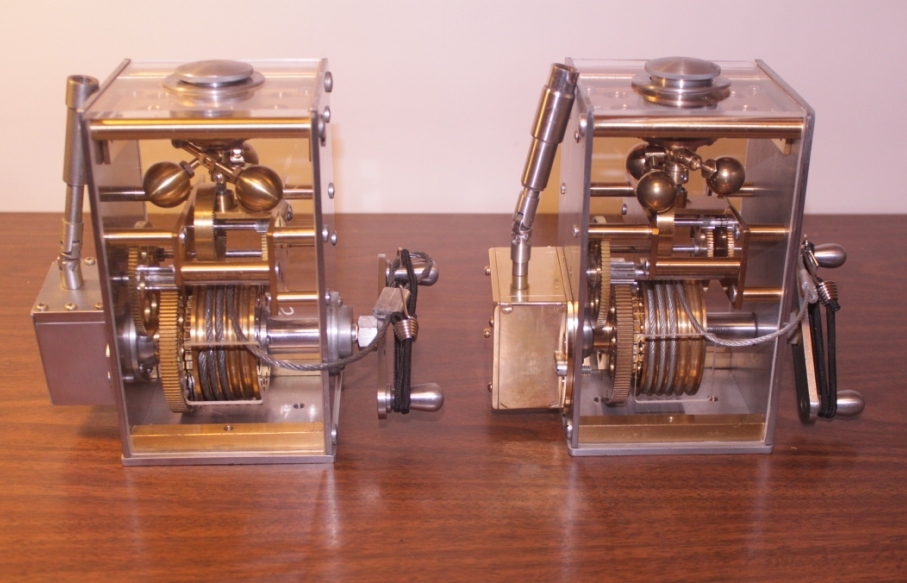
On the right is the restored drive with the replica ball governor and recently completed gear housing box. To duplicate the factory motion transmission system I started by measuring those parts on the original. I matched them as closely as possible to standard gears from the Boston Gear catalog. To make the components I had to modify some of the Boston gears extensively by boring them and reducing their diameters. My primary goal was to match the performance of the Unitron drive as closely as possible and the appearance was a secondary consideration.
You can see from the picture that I made the gear housings using brass. Here are some pictures:
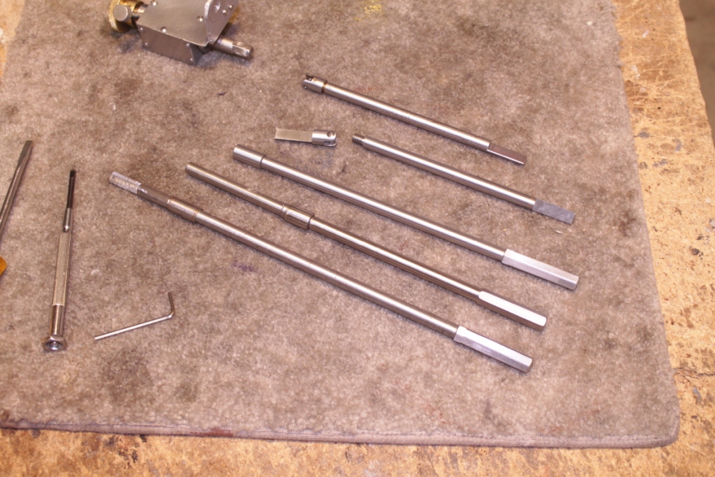
I used stainless steel for the shafts, mostly for strength. As a bonus, the stainless steel closely matches the original Unitron nickel finish. There are many more details of the construction and a teardown video on my Youtube Channel at https://www.youtube.com/watch?v=NAM-nHNfn9s&feature=youtu.be .
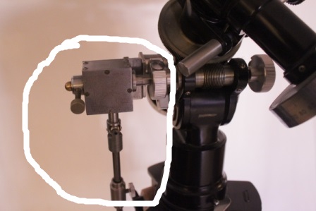
A complete four inch Unitron is too large for my house so I have opted to place a three inch on display in my office. I made a custom set of legs and tripod spreader so I can mount the restored weight drive on the three inch. I originally set that up strictly for display purposes but have found that the weight drive can be “tuned” to a proper rate for the three inch mount. I made the mounting hardware interchangeable between the three inch and the four inch. You can see all of this in operation in my video at http://youtu.be/M3Ch5DAFHv8 . If you have ever wondered what it is like to “tune” one of these drives you can get a hint of the process in the video.
It is very handy to have a selection of different length connecting rods so one has more flexibility in arranging the mount.
Depending on how you align the polar axis with respect to the tripod legs, there may be an interference problem with the tripod. As you rotate the equatorial head the clearance for the coupling rods changes. That rotation also necessitates a different length coupling rod system. That is one reason for the sliding hexagonal coupler. But, that sliding coupler only permits an adjustment of about an inch. So using different combinations of coupling rods allows for a lot more flexibility.
The coupling system shown in the video works fine but is is not quite up to Unitron standards so I plan on making more appropriate U-joints soon. Stay tuned!